In this first project, we’ll build a simple LED circuit – the perfect starting point for anyone new to electronics. This basic circuit will teach you fundamental concepts while giving you the satisfaction of seeing your creation light up.
Parts needed:
-
- LED (we’ll be using two different types)
-
- Resistors
-
- 9V battery
-
- Breadboard
-
- Connecting wires
-
- Multimeter
Let’s get building!
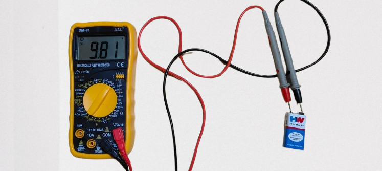
Now that we have our components ready, the first step is to check our battery. I’m using a 9V battery for this project, which is more than enough to power an LED. Using a multimeter set to DC voltage, I measured my battery at 9.81V – perfect for our needs. Always check your power source before starting any electronics project to avoid frustration. A reading above 9V indicates a fresh battery, while anything below 7V might not provide optimal results.
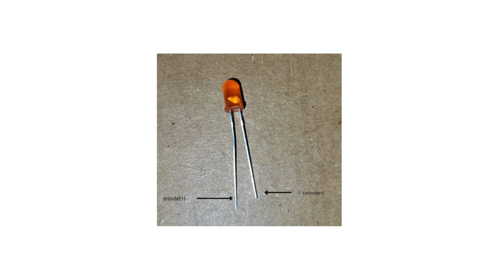
LEDs (Light Emitting Diodes) have polarity, meaning they only work when connected in the correct direction. You can identify the positive terminal (anode) and negative terminal (cathode) in several ways. The most reliable method is to look at the legs – the longer leg is always the anode (positive), while the shorter leg is the cathode (negative).Getting the polarity right is crucial – if you connect an LED backwards, it won’t light up and could potentially be damaged.
Now that we understand how to properly connect our LED, we need to determine the right resistor value to protect it. LEDs need current limitation because they have very low internal resistance. Without a resistor, too much current would flow through the LED, causing it to burn out almost instantly. If you have a multimeter with a diode test function, you can measure the exact forward voltage of your LED by setting the multimeter to diode test mode (▶|), connecting the red probe to the anode and the black probe to the cathode.
However, if you don’t have this function, you can rely on standard values – red LEDs typically have a forward voltage of about 1.8-2.2V. To calculate the appropriate resistor value,
we use Ohm’s Law: R = (Vsupply – Vled) / I, where Vsupply is our battery voltage (9.81V).
Vled is the forward voltage of our red LED (approximately 2V), and
I is our desired current (typically 20mA or 0.02A for standard LEDs).
Plugging in these values: R = (9.81V – 2V) / 0.02A = 390.5Ω.
Since resistors come in standard values, our 330Ω resistor is close enough and will work perfectly for this circuit, allowing the LED to shine brightly while preventing damage from excessive current.
Building the Circuit
Now let’s put all these components together to create our working LED circuit. The path of current flow in our circuit will be:
Positive terminal of battery → Resistor → LED anode (longer leg) → LED cathode (shorter leg) → Negative terminal of battery
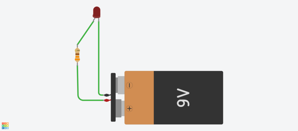
With our 9V battery, 330Ω resistor, and red LED, I assembled the circuit on a breadboard as shown in the image below:
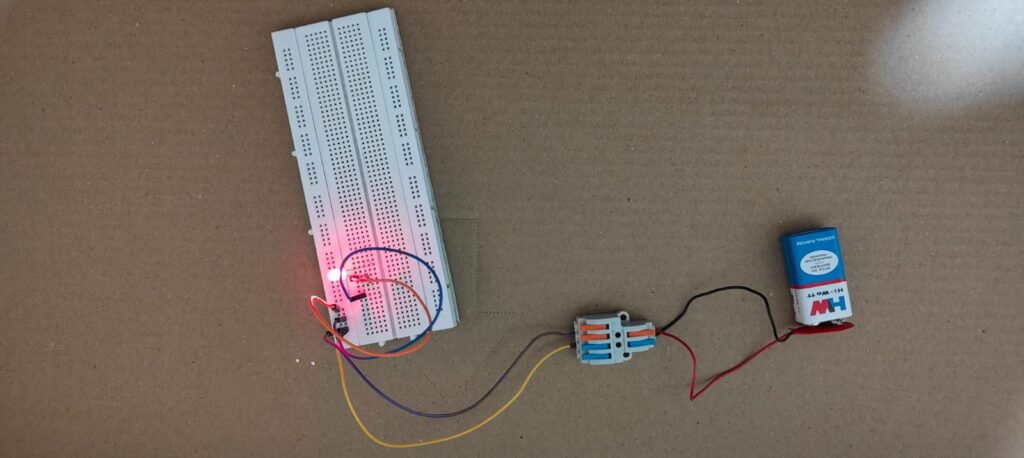
The breadboard makes it easy to connect components without soldering. When you connect everything correctly, the LED should light up immediately. If your LED doesn’t illuminate, check the following:
-
- LED polarity – Make sure the longer leg (anode) is connected to the resistor
-
- Battery connections – Verify both terminals are properly connected
-
- Resistor placement – Ensure it’s in line with the circuit
-
- Battery charge – Confirm your battery has sufficient voltage
What’s Happening in Our Circuit?
When the circuit is complete, electrons flow from the negative terminal of the battery through the LED, causing it to emit light. The resistor ensures that only the right amount of current passes through the LED. This simple circuit demonstrates fundamental principles of electronics:
-
- Current requires a complete path (circuit)
-
- Components like LEDs have polarity
-
- Resistors control current flow
-
- Voltage drops across components
Conclusion
Congratulations! You’ve successfully built your first LED circuit and learned some fundamental electronics concepts along the way. This simple project introduces the basic principles that govern all electronic circuits – current flow, voltage, resistance, and component polarity.
Understanding how to properly power an LED is the first step toward more complex electronics projects. The skills you’ve learned here – calculating resistor values, identifying component polarity, and creating a complete circuit – will serve as building blocks for future projects.
As you continue your electronics journey, remember that even the most complicated devices are built upon these same basic principles. Start simple, learn the fundamentals, and gradually build your knowledge and skills.