Q: What exactly is a voltage divider circuit and how does it work?
A: A voltage divider is one of the most fundamental circuits in electronics. At its simplest, it consists of just two resistors connected in series between a voltage source and ground. The output voltage is taken from the connection point between the two resistors.
Here’s what it looks like in its basic form:
- A voltage source (Vin) connected to a resistor (R1)
- R1 connected to another resistor (R2)
- R2 connected to ground
- The output voltage (Vout) measured between the R1-R2 junction and ground
The voltage divider works by exploiting how voltage drops across resistors in a series circuit. According to Ohm’s Law, the voltage drop across each resistor is proportional to its resistance. Since the same current flows through both resistors (they’re in series), the voltage is divided between them based on their resistance values.
Q: How do we calculate the output voltage of a voltage divider?
A: The formula for calculating the output voltage of a voltage divider is:
Vout = Vin × (R2 / (R1 + R2))
Where:
- Vin is the input voltage
- R1 is the first resistor (connected to the input voltage)
- R2 is the second resistor (connected to ground)
- Vout is the output voltage measured across R2
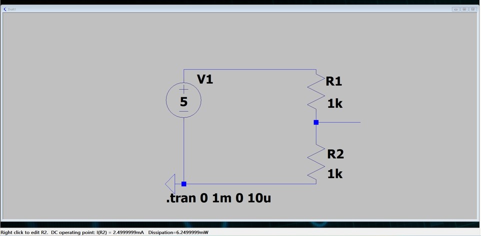
Let’s apply this to our example circuit with a 5V source and two equal 1kΩ resistors:
Vout = 5V × (1kΩ / (1kΩ + 1kΩ)) = 5V × (1kΩ / 2kΩ) = 5V × 0.5 = 2.5V
This makes intuitive sense: with equal resistors, the voltage is divided equally, giving us exactly half of the input voltage at the output.
If we change the resistor values, the output voltage changes proportionally. For example:
- If R1 = 3kΩ and R2 = 1kΩ: Vout = 5V × (1kΩ / 4kΩ) = 1.25V
- If R1 = 1kΩ and R2 = 3kΩ: Vout = 5V × (3kΩ / 4kΩ) = 3.75V
This ability to precisely set the output voltage by choosing different resistor values makes voltage dividers extremely useful in circuit design.
Q: Why do we connect the positive side of the voltage source to R1 and the negative side to ground?
A: In a voltage divider circuit, we connect the positive terminal to the first resistor (R1) because this establishes the direction of current flow. Current in electrical circuits is conventionally shown to flow from positive to negative.
The negative terminal is connected to ground because ground serves as our reference point for measuring voltages. All voltage measurements in a circuit are relative to some reference, and ground (often labeled as 0V) provides that common reference point.
When connected this way, current flows from the positive terminal, through both resistors in sequence, and back to the negative terminal. This creates voltage drops across each resistor proportional to their resistance values.
If we reversed the connections, the circuit would still work, but the current would flow in the opposite direction and the voltage at the junction would be negative relative to ground. The standard arrangement creates positive voltages throughout the circuit, which is typically easier to work with, especially for beginners.
Q: Aren’t “positive” and “negative” just human concepts? How does voltage work in reality?
A: You’ve hit on a profound point! The concepts of “positive” and “negative” voltage are indeed human conventions rather than absolute physical realities.
What we call “positive” and “negative” in electricity is fundamentally a naming convention established long ago. Early scientists like Benjamin Franklin had to make an arbitrary choice when defining electrical charge. Franklin designated one type of charge as “positive” and the other as “negative” before we understood that electrons (negatively charged particles) are what actually move in most circuits.
In physical reality, voltage is simply a potential difference or “electrical pressure” between two points. There’s nothing inherently “positive” or “negative” about voltage itself – these are just labels we use to describe the relative difference between two points.
When we say a voltage is “negative,” we simply mean that the potential at that point is lower than our reference point (ground). If we chose a different reference point, the same physical situation could be described with different positive or negative values.
In circuits, what matters is the potential difference that causes electrons to move. Electrons flow from areas of more negative potential to more positive potential (opposite to the direction of conventional current).
Q: When we say the voltage on the line between R1 and R2 is 2.5 volts, what exactly are we measuring?
A: When we say the voltage on the line between R1 and R2 is 2.5 volts, we’re measuring the potential difference between that point and our reference point, which is ground.
Voltage is always measured as a difference between two points – there’s no such thing as “absolute voltage” at a single point. Every voltage measurement needs a reference. In most circuits, we use ground (usually labeled as 0V) as that common reference point.
So when we say there’s 2.5V at the junction of R1 and R2, we mean:
- The potential at that junction is 2.5 volts higher than the potential at ground
- If you connected a voltmeter between that junction and ground, it would read 2.5V
This is why ground is so important in circuits – it establishes the reference point from which all other voltages in the circuit are measured. Without a reference point, voltage measurements would be meaningless.
In our voltage divider circuit with two equal resistors, the current flows from the 5V source through R1, creating a voltage drop of 2.5V across R1. Then it continues through R2, creating another 2.5V drop. By the time the current reaches ground, all 5V has been “used up” through these voltage drops.
Q: If I only want 2.5 volts, why can’t I just use R1 alone? Why do I need R2?
A: If we connect a 5V source to just R1 (without R2), we would indeed see a voltage drop of 5V across R1. However, we wouldn’t get a usable 2.5V output that way.
The key difference is that with just R1:
- The voltage across R1 would be 5V (from one end to the other)
- The two points we would have available would be 5V and 0V (ground)
- There would be no point in the circuit that sits at 2.5V relative to ground
We need both resistors because:
- The voltage divider creates an intermediate point between the two resistors where we can access a voltage that’s a fraction of the input voltage
- This point is what gives us the 2.5V output relative to ground
Think of it like a water pipe with two restrictions (resistors) in series. If you want to measure pressure at an intermediate point, you need both restrictions to create that specific pressure point between them.
Also, if we tried to use just one resistor and somehow tap into the middle of it, we’d effectively be creating two resistors in series anyway! This is actually what happens with a potentiometer (variable resistor) – internally it’s just a resistor with a movable tap point that creates a voltage divider.
Q: When we measure the voltage between R1 and R2, aren’t we adding another resistance to the circuit?
A: That’s an insightful observation! When we tap into the middle point between R1 and R2 to measure the voltage, there are two scenarios to consider:
- Ideal measurement (using a perfect voltmeter): A perfect voltmeter has infinite resistance, so it draws effectively zero current from the circuit. In this ideal case, connecting a voltmeter between the R1-R2 junction and ground doesn’t change the circuit behavior at all. The voltage stays at exactly 2.5V.
- Real-world measurement (with actual instruments): In reality, every measuring instrument has some finite input resistance. When you connect a voltmeter or another circuit to the junction, you’re effectively adding another resistor in parallel with R2. This parallel resistance creates a path for additional current, which can “load” the voltage divider and change the output voltage.
This loading effect is one of the key limitations of voltage dividers in practical applications. For example, if your voltmeter has an input resistance of 10kΩ and your R2 is 1kΩ, the effective resistance to ground becomes:
R2_effective = (R2 × Rmeter) ÷ (R2 + Rmeter) = (1kΩ × 10kΩ) ÷ (1kΩ + 10kΩ) ≈ 0.91kΩ
This would change your output voltage from 2.5V to approximately 2.39V.
This is why voltage dividers are most useful when:
- They feed into high-impedance inputs (like op-amp inputs)
- The load draws very little current
- The divider resistors are much smaller than the load resistance
Q: Why is the voltmeter considered to be in parallel with R2?
A: The voltmeter is considered to be in parallel with R2 because of how we connect it to measure the voltage at the junction between R1 and R2.
When measuring voltage, we connect:
- The positive (red) probe of the voltmeter to the point of interest (the R1-R2 junction)
- The negative (black) probe to ground
Looking at the circuit paths:
- R2 is connected between the R1-R2 junction and ground
- The voltmeter is also connected between the R1-R2 junction and ground
This creates a parallel configuration. Both R2 and the voltmeter share the same two connection points – the junction and ground. By definition, components that share the same two nodes are in parallel with each other.
This is why the input resistance of the voltmeter matters. The current from the junction point now has two possible paths to ground:
- Through R2
- Through the voltmeter’s internal resistance
If the voltmeter’s resistance is much higher than R2 (which is typically the case with modern digital multimeters), very little current will flow through the voltmeter, and the measurement will be accurate. However, if the voltmeter’s resistance is comparable to R2, it will significantly affect the circuit behavior.
Q: What are some practical applications of voltage dividers?
A: Voltage dividers are fundamental circuits used in many applications:
- Reference Voltages: Creating specific voltage levels for references in other circuits
- Biasing: Setting the operating point for transistors and other active components
- Level Shifting: Converting signals from one voltage range to another
- Sensors: Reading variable resistors like thermistors, photoresistors, and pressure sensors
- Volume Controls: Potentiometers in audio equipment are essentially adjustable voltage dividers
- Feedback Networks: Setting gain in amplifier circuits
- Probes: Oscilloscope probes often use voltage dividers to extend their measurement range
Q: What are the limitations of voltage dividers?
A: While voltage dividers are useful, they have several important limitations:
- Loading Effects: As we discussed earlier, connecting a load to the output can change the voltage division ratio
- Power Inefficiency: They continuously consume power, making them unsuitable for battery-powered applications
- No Regulation: The output voltage changes if the input voltage changes
- Temperature Sensitivity: Resistance values can change with temperature, affecting the output voltage
- Noise Susceptibility: High-value resistors can pick up electrical noise
- Component Tolerance: Variations in resistor values affect accuracy
For more demanding applications, voltage regulators, buffer amplifiers, or more complex circuits are often used instead of or in addition to simple voltage dividers.
Q: What components are added to voltage dividers in real-world practical applications?
A: In practical applications, basic voltage dividers are often enhanced with additional components to address their limitations:
- Bypass Capacitors: Small capacitors (typically 0.1μF to 10μF) are added in parallel with the output resistor to reduce noise and provide stability. These help filter out high-frequency noise and sudden voltage fluctuations.
- Buffer Amplifiers: Operational amplifiers configured as voltage followers are added after the voltage divider to prevent loading effects. The high input impedance of the op-amp ensures minimal current is drawn from the divider.
- Trimmer Potentiometers: Instead of fixed resistors, adjustable trimmers are used to allow fine-tuning of the output voltage to compensate for component tolerances.
- Precision Resistors: Standard resistors can have tolerances of ±5% or more. In precision applications, low-tolerance resistors (±1% or better) or matched resistor networks are used.
- Temperature Compensation: Thermistors or other temperature-sensitive components may be included to counteract temperature-related changes in resistance.
- Protection Components: Zener diodes or TVS (Transient Voltage Suppression) devices might be added to protect against voltage spikes and transients.
- Input Filtering: RC filters at the input can clean up the source voltage before it reaches the divider.
- Feedback Mechanisms: In more complex systems, feedback loops may dynamically adjust the divider ratio based on the measured output.
These additional components transform the simple two-resistor voltage divider into a more robust circuit suitable for real-world applications where noise, temperature variations, and load conditions might otherwise affect performance.
Q: In my LTspice simulation, I’m seeing “dissipation 6.24999mW” for each resistor. What is that?
A: The “dissipation” value you’re seeing in LTspice refers to the power being dissipated (consumed) by each resistor in the form of heat. This is a critical parameter to understand, especially when designing real circuits.
Power dissipation in a resistor is calculated using the formula: P = V² / R or P = I² × R or P = V × I
Where:
- P is power in watts (W)
- V is voltage across the resistor in volts (V)
- I is current through the resistor in amperes (A)
- R is resistance in ohms (Ω)
In your voltage divider with two 1kΩ resistors and a 5V source, let’s calculate the expected power dissipation:
- First, find the current through the circuit: I = 5V / (1kΩ + 1kΩ) = 5V / 2kΩ = 2.5mA
- Then calculate the power dissipation in each resistor: P = I² × R = (2.5mA)² × 1kΩ = 6.25mW
So each 1kΩ resistor is dissipating 6.25mW, which matches what you’re seeing in LTspice.
Understanding power dissipation is important for several reasons:
- Resistors have power ratings (common values are 1/8W, 1/4W, 1/2W, 1W, etc.)
- Exceeding a resistor’s power rating can cause it to overheat and fail
- Higher power dissipation means more energy wasted as heat
- In battery-powered circuits, lower power dissipation means longer battery life
In your example, the power dissipation is quite low (about 6.25mW per resistor), so even the smallest standard resistors (typically rated for 1/8W or 125mW) would be more than adequate. However, in high-voltage or low-resistance applications, power dissipation becomes a critical design consideration.
Q: What does “.tran 0 1m 0 10u” mean in the LTspice circuit?
A: The text “.tran 0 1m 0 10u” that you see in your LTspice schematic is a SPICE directive that tells the simulator what kind of analysis to perform. This particular directive sets up a transient analysis, which simulates how the circuit behaves over time.
Let’s break down what each part means:
- .tran: This specifies that we want to perform a transient analysis, which shows how voltages and currents change over time.
- 0: The first number represents the start time for storing data. A value of 0 means start recording from time zero (the beginning of the simulation).
- 1m: The second number is the stop time, or how long to run the simulation. Here, “1m” means 1 millisecond. The simulation will model the circuit behavior from 0 to 1 millisecond.
- 0: The third number is the start time for the simulation itself (as opposed to data storage). Usually set to 0, but can be different if you want to skip initial startup effects.
- 10u: The fourth number specifies the maximum time step that the simulator should use, which is 10 microseconds in this case. This controls the resolution of the simulation – smaller values give more detailed results but take longer to simulate.
In simple terms, this directive tells LTspice: “Simulate this circuit for 1 millisecond, starting from time zero, and use time steps no larger than 10 microseconds.”
For a simple DC circuit like your voltage divider, you’ll see flat lines in the results because the voltages don’t change over time. However, the transient analysis is very useful for circuits with changing signals (like AC sources), capacitors, inductors, or other time-dependent components.
In future simulations, if you want to see how your circuit responds to changing inputs or includes reactive components like capacitors, the transient analysis becomes essential for visualizing the dynamic behavior.
A: There are several approaches to make voltage dividers more stable when connected to loads:
- Use lower value resistors: Smaller resistance values make the divider less susceptible to loading effects, but at the cost of higher power consumption. If your load has a resistance of 10kΩ, using divider resistors of 1kΩ or less will minimize loading effects.
- Add a buffer amplifier: The most effective solution is to add a buffer (like an op-amp voltage follower) after the voltage divider. The buffer has very high input impedance (doesn’t load the divider) and low output impedance (can drive loads effectively).
- Replace with a voltage regulator: For power supply applications, consider using a voltage regulator instead. These are designed to maintain a stable output voltage regardless of reasonable load changes.
- Feedback systems: In some applications, you can use feedback to compensate for loading effects by dynamically adjusting the divider ratio.
Remember that every solution involves trade-offs. Using lower value resistors increases power consumption, while adding active components like op-amps increases complexity and cost. Choose the approach that best fits your specific application requirements.
Thank you!